Ultimate Strength
Conventional ships (bulk carrier, oil tanker, container vessel) and offshore structures are very complex systems mainly composed of steel plate panels, stiffeners, girders and frames. To validate calculation methods for ultimate strength assessment, experimental results delivered for corresponding models are of essential importance. At the Chair of Ship Structures ultimate strength tests are performed for different beams and box girder specimens.
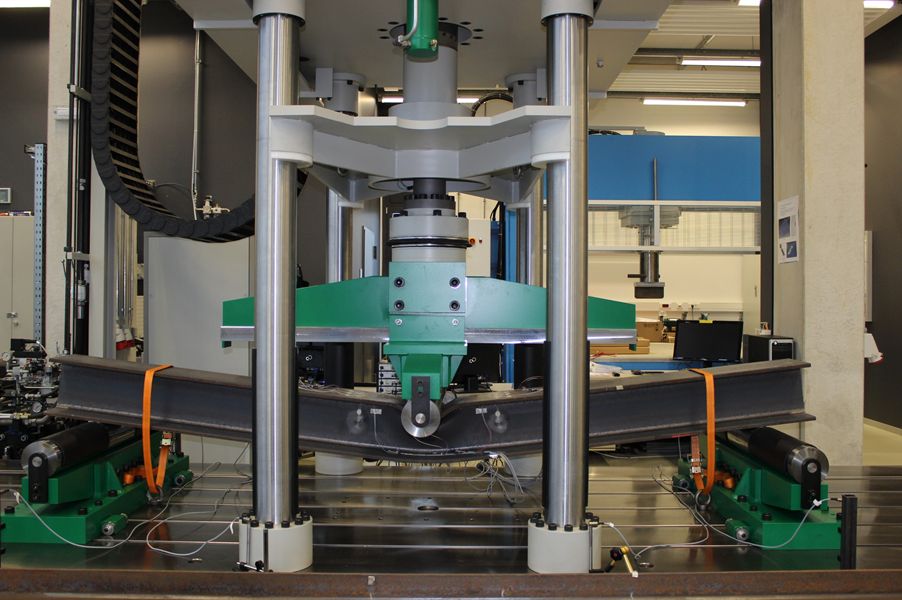
The Hydraulic Test Rig System was used to analyse the collapse behaviour of different symmetric I-beams in 3-point and 4-point bending experimentally. The hot rolled I-beams consisting of mild steel are investigated separately and characterized by an overall length of 3.5m. Each beam is simply supported at the lower flange side by two steel rolls. Depending on the bending test the loading is applied to the upper flange side by one or two laterally moving steel rolls. To apply a quasi static load on the beam structures a constant piston velocity of 0.05mm/s is provided. Due to the specifications of the Hydraulic Test Rig System the ultimate strength tests are performed successfully and appropriate finite beam element models are validated to simulate progressive collapse behaviour. To analyse the ultimate strength of structures under dynamic loads the influence of the strain rate on the yield properties of metals has to be considered. Therefore, uniaxial tensile tests are performed for different mild and high tensile steel specimens to determine the corresponding dynamic yield strength.
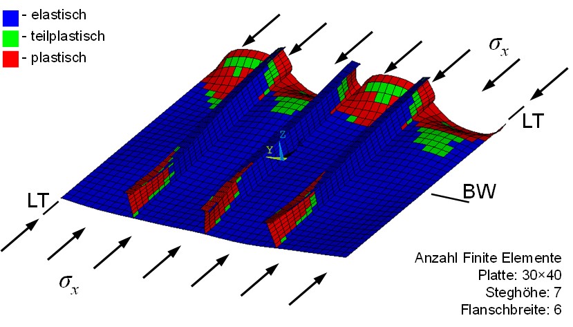
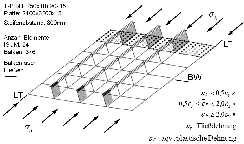
The Hydraulic Test Rig System was used to analyse the collapse behaviour of box girder specimens in 4-point bending. The specimens are composed of plate panels with a large slenderness ratio, longitudinal flat bar stiffeners and two transverse frames. At both ends rigid transverse frames are attached to connect the specimen with the loading structures. The loading structures are identical to each other and consisting of high tensile steel components. Due to the dimensions and the material properties they always keep elastically within the load application range of the Hydraulic Test Rig System. The entire structural system is simply supported at the lower left and right end by freely rotating steel rolls. A constant bending moment is applied to the specimen by two laterally moving steel rolls located on the upper side of the loading structures. Due to the specifications of the Hydraulic Test Rig System the ultimate strength tests are performed successfully and appropriate numerical models are validated to simulate progressive collapse behaviour of box girder specimens.
Contact:
Prof. Dr.Eng./Hiroshima Univ. Patrick Kaeding
Dr.-Ing. Thomas Lindemann