Hydraulic Test Rig System
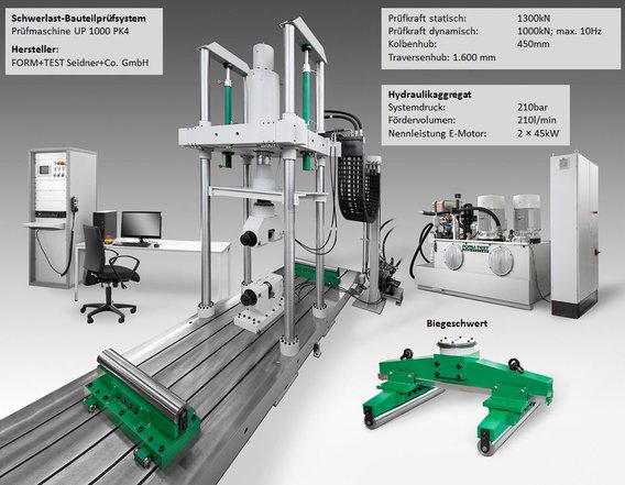
Today, a huge amount of different kinds of software packages is applicable to simulate the physical behaviour of complex structural systems. However, to investigate the fundamentals and to validate numerical models experimental results are still of essential importance. The Chair of Ship Structures is in possession of a Hydraulic Test Rig System to analyse the static and the dynamic behaviour of large structural systems. Different setups of the testing machine are feasible to perform for example uniaxial tensile tests, 3-point and 4-point bending tests. The ingredients and corresponding specifications of the Hydraulic Test Rig System are given in the figure below.
The main dimensions of the Hydraulic Test Rig System are given by the overall length of 6m, width of 2.5m and height of 5.85m. The testing machine is a closed frame structure to apply high values of positive or negative static and dynamic loads to large structural systems. The base plate of the machine is supported by 8 pneumatic buffer elements, which are controlled automatically during the loading history. On the base plate 4 steel columns are fixed. Furthermore, a traverse can move laterally between the columns. When the final testing position is reached, the traverse will be fixed automatically to the columns. On the traverse a hydraulic cylinder is located to apply the loads to the specimen. The required loads are generated by one or even by two separate working hydraulic units at a maximum pressure of 210bar. The loading of the specimen can be applied by force control as well as by displacement control.
The Hydraulic Test Rig System has been funded by the DFG (German Research Foundation) and the German state of Mecklenburg-Vorpommern. It has been built by FORM+TEST Seidner&Co. GmbH.
Contact: Prof. Dr.Eng./Hiroshima Univ. Patrick Kaeding
Andreas Stawski, M.Sc.